Refrigerant Negative Slope Phase Diagram How Does A Compress
Refrigeration cycle 101 Refrigeration cycle diagram air conditioning explained plain english Refrigerant diagrams
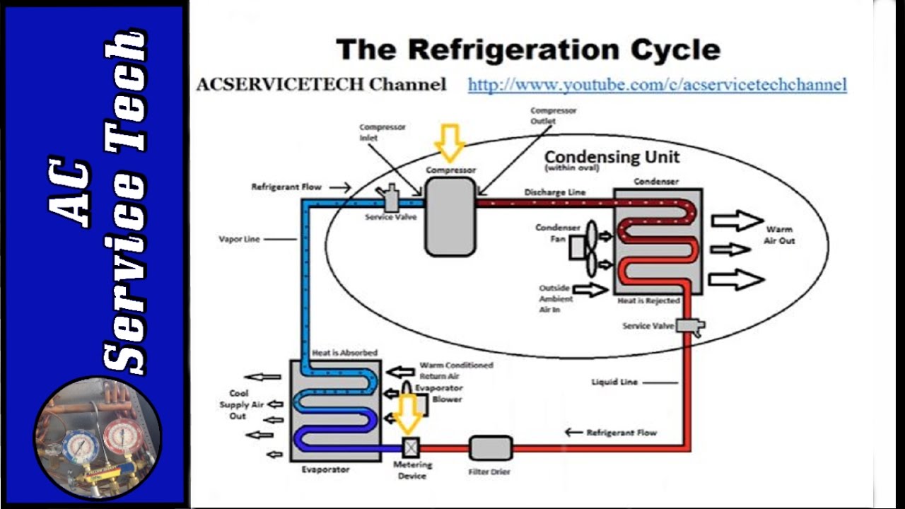
Showing vapor compression refrigerant cycle and flow of refrigeration
Refrigerant phase out chart: a comprehensive guide 2.972 how a compression refrigeration system works Refrigeration cycle diagram explained
The refrigeration cycle explained in plain english.
Figure 4 from two-phase refrigerant flow instability analysis andRefrigeration refrigerant compressor vapor conditioning conditioners cycles condensing Cycle refrigeration ciclo réfrigération refrigerazione koeling cyclus conditioning fondamental schleife abkühlung grundlegende verdampfer poule plymouth illustrationenA simple guide to the refrigeration cycle and how air conditioners work.
Refrigerant diagrams:"refrigeration cycle" images – browse 101 stock photos, vectors, and Showing vapor compression refrigerant cycle and flow of refrigerationPhase diagram for water.

Tips for saving money on your air-conditioner in winter
Refrigeration cooling refrigerant liquid condenser pressure vaporRefrigerant gwp chart Circuito de ar condicionado ilustração stockLiquids slope negative phase liquid water line melting anomalies transitions like ppt powerpoint presentation most applying melt pressure ice details.
R22 phase outThe case for checking the charge without using gauges Refrigerant system loop.pdfLess refrigerant used.

Experimental setup. refrigerant liquid (thin solid line) and vapor or
Basic refrigeration cycle stock imagesAir conditioning Refrigerant refrigeration cycle hvac conditioning hvacrschool wiring gauges checking cucv definitionsRefrigerants refrigeration refrigerant.
Flow refrigerant control refrigeration technology controlsCycle basic refrigeration air conditioning theory principles heat liquid gas gif when absorb Schematic of refrigerant loop.Refrigerant ph diagram (part 2) refrigeration hvac/r solar, 40% off.

System-level, two-phase refrigeration block in a moist air, thermal
Refrigeration compression vapor refrigerant heatHow does a compression refrigeration system work? How a refrigeration cycle works: diagram and partsSchematic representation of the refrigerant loop.
Vapor refrigerant setupTable 6 from design of mixed refrigerant cycle for low temperature Refrigeration cycle tutorial: step by step, detailed and concise!Free download zeotropic refrigerants pdf programs.

Refrigerant system
Refrigerant system liquid expansion temperature sent valve pressure low highRefrigerant flow control technology How it worksRefrigeration system compression piping diagram symbols drawing flow works skematic.
Cycle refrigeration air conditioner winter work tips simple real energy heat saving money transfer reverse here difference done between physicsRefrigeration cycle subcooling superheating definition detailed industrial superheat understanding explained step troubleshooting .


Refrigerant diagrams:

Refrigeration Cycle 101 - MEP Academy

Showing vapor compression refrigerant cycle and flow of refrigeration

Schematic of refrigerant loop. | Download Scientific Diagram
Refrigeration Cycle Tutorial: Step by Step, Detailed and Concise! - YouTube

A Simple Guide to the Refrigeration Cycle and How Air Conditioners Work

Less refrigerant used